Super Shroud™ Assembly Manual
Formats Available
Super Shroud Online Manual
Tools, Materials and Hardware
Tools:
- Precision Bubble Level
- Socket Wrench with ½” and 9/16” sockets
- ½” and 9/16” open end wrench (1 each)
- 7/8” and 1-1/16” open end wrench (2 each)
- #3 Philips Screwdriver
- Tape measure
- Adjustable Torque Wrench
Materials:
- Upper Mounting Bracket (3 pieces)
- Lower Mounting Bracket (3 pieces)
- Upper Rotating Assembly
- Lower Rotating Assembly
- Panels (3 total – Fixed, Latch and Floating)
- Hinge Rods (2 pieces)
Hardware (Included):
- 6ea. 5/8-11 x 6” A325 Galvanized Bolt (Pole Mount to Tower)
- 12ea. 5/8” Galvanized Flat Washers (Pole Mount to Tower)
- 6ea. 5/8” Galvanized Split Washers (Pole Mount to Tower)
- 6ea. 5/8-11 Galvanized Nuts (Pole Mount to Tower)
- 6ea. ½-13 x 12” threaded rod (Ring Assembly to Pole Mount)
- 24ea. ½” Galvanized Flat Washer (Ring Assembly to Pole Mount)
- 6ea. ½” Galvanized Split Washer (Ring Assembly to Pole Mount)
- 30ea. ½” Galvanized Nuts (Ring Assembly to Pole Mount)
- 18 ea. 3/8-16 x 1” Flat Head Philips Machine Screw, 316SS (Panel to Ring Assembly)
Torque Table
| Section | Fastener | Torque | Notes |
| Tower Mounts – 3 arm mount clamping around tower spine | 5/8″- 11 A325 Galvanized Bolt and Nut | 147 foot-lbs | Caution: ASSUMES SCHEDULE 40 or 80 STEEL SPINE |
| Tower Mounts – 3 arm mount to aluminum ring | 1/2″- 13 Galvanized Threaded Rod and Nut | 37 foot-lbs | |
| Aluminum ring assembly, ½” tie bar plates | ½-13 Stainless Steel 316 Bolt into 6061 Aluminum Plate | 36 foot-lbs | |
| Aluminum ring assembly, 90 degree bracket attachment | 5/16-18 Stainless Steel 316 Bolt into 6061 Aluminum Plate | 12 foot-lbs |


Installation Steps
General Layout Considerations
The Super Shroud consists of the 3 piece fiberglass tube, the upper and lower rotating ring assemblies, and the upper and lower pole mount assemblies (refer to image on Page 2). The first step is to determine the desired vertical position of the shroud itself. Mark the top and bottom of the shroud on the tower with masking tape. The ring assemblies sit 1 inch inboard from the top and bottom of the panels. This is dictated by the pre-drilled fiberglass panels and is not adjustable without special order panels. The mounts that hold the ring assemblies can be placed above or below each ring assembly. They can be placed directly against the rings or spaced apart to allow shimming with extra nuts and washers. For ease of installation, this is the suggested method. These decisions are up to the installer and site requirements. Some considerations:
- Space inside the shroud for antennas, etc.
- Concealment of the mounts
- Interference with other equipment on the tower
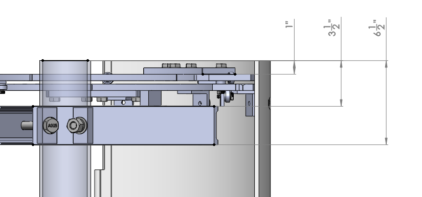
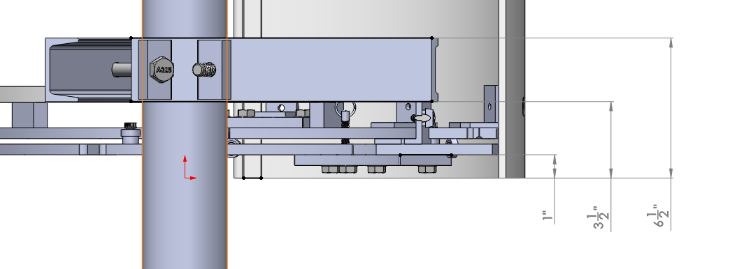
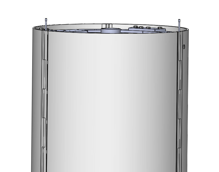
The following images show a suggested layout that places the upper and lower mounts inside the shroud and allows for easy fine tuning of height and level using threaded rods and nuts.
Top Of Shroud
Bottom of Shroud
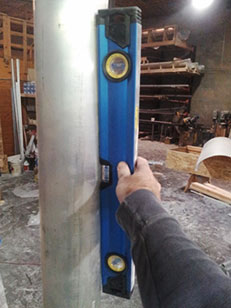
Prepare The Pole
Before install verify that the pole is plumb
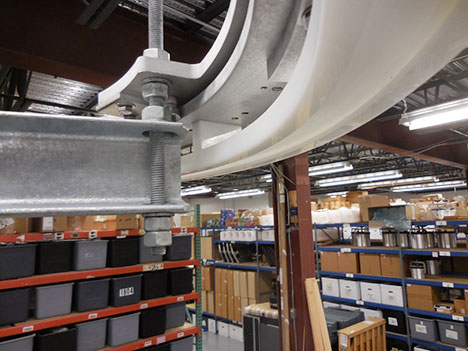
Step 1 – Install The Tower Mounts
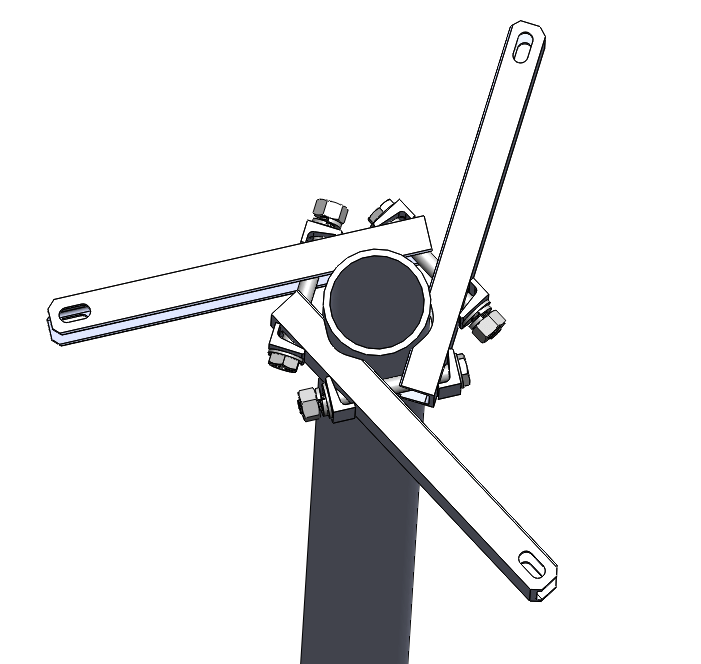
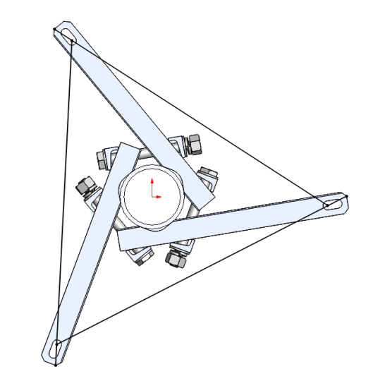
Assemble the top pole mount using the supplied 5/8” galvanized hardware: 3 each of mount arm, 6” bolt, flat washer, split lock washer, nut.
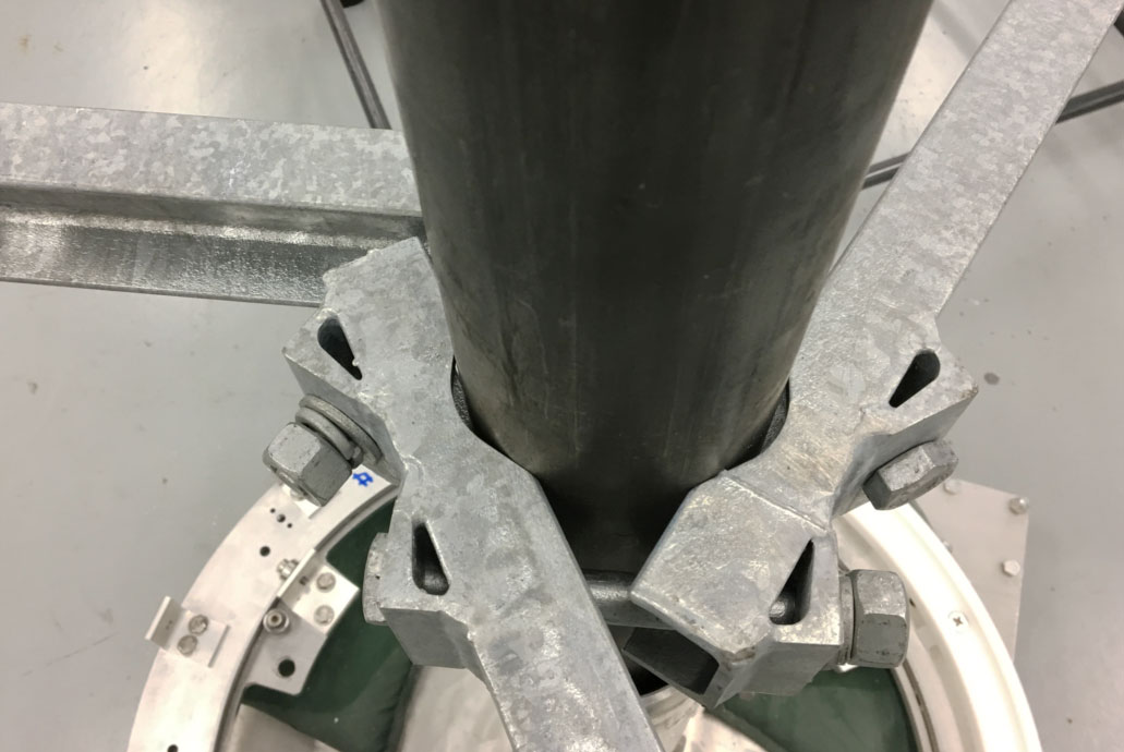
The three bolts should be tightened evenly to maintain 120 degree angular spacing between the three bars. Once the bolts are tightened the distance between the oval slots should be equal.
Note: One trick to assemble these three pieces around the tower is to tighten a large C-clamp to the tower just below where you will place the mount. This provides a bit of a platform to rest the steel pieces on until you start tightening the three bolts.
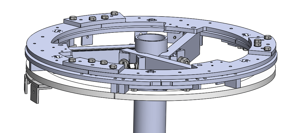
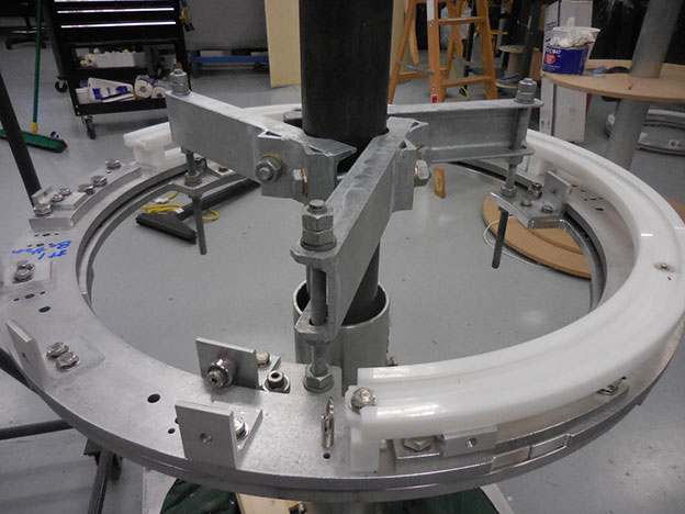
Step 2 – Install The Upper Ring Assembly
If you have unobstructed access to the top of the tower it is possible to install the upper ring fully assembled. If you have access from the top of the tower all the way to the bottom of the shroud it is possible to lift the lower ring assembly over the tower and lower it down into place without disassembly. Either of these situations will simplify installation. If you do not have access to place the rings over the top of the tower you will need to dis-assemble the rings and then re-assemble them in place. In this case, see STEP 2-B. The upper ring assembly will be marked TOP or UPPER. It is the one without the rotation lock spring plunger. The upper ring assembly is positioned with the plastic track facing the ground. As discussed in General Layout Considerations, it can be placed and bolted directly to the Upper Pole Mount arms or it can be suspended from the Upper Pole Mount using threaded rods. A direct attachment takes up less vertical space. A threaded rod attachment makes it much easier to level and adjust the ring assembly.
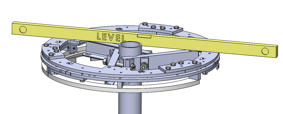
A precision level should be placed across the top of the fixed ring to be sure the ring assembly is level in all directions. You can either adjust the 3 arm mount or the nuts on the threaded rod to make the ring assembly level. Verify it is level in all directions.
It is important to position the ring assembly concentric with the spine of the tower. The plastic alignment guide allows you to align the inside or outside edge of the ring assembly to check concentricity. 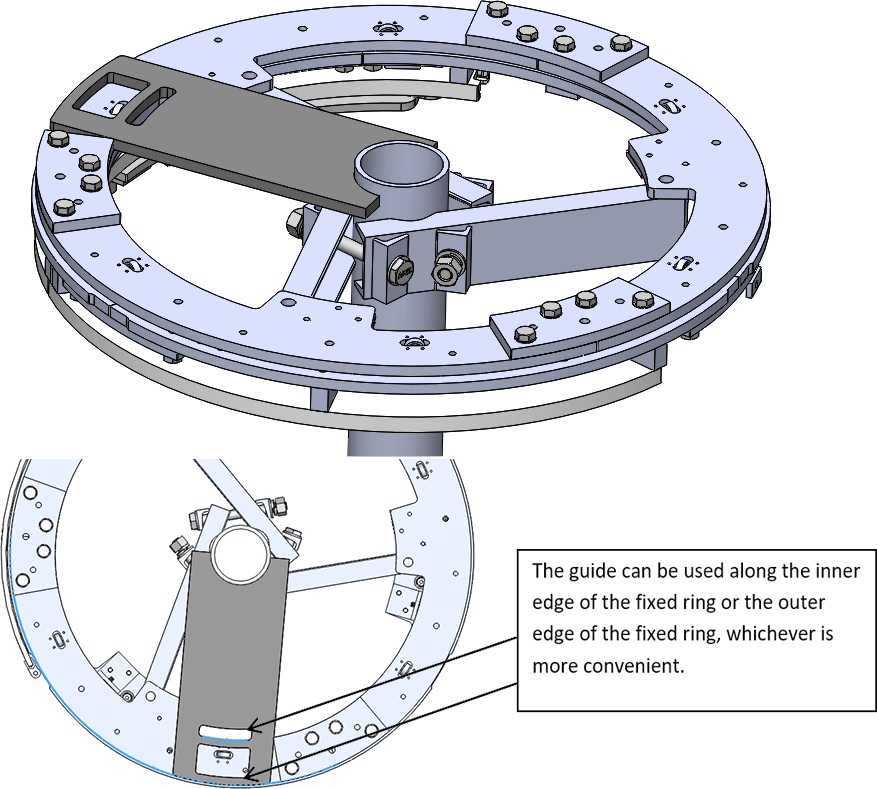 You should check it in multiple places around the ring. Be sure the alignment jig nests tightly against the tower pole. If it does not then you will need to use a tape measure to check concentricity of the rings. When the ring assembly is level and concentric then tighten the nuts to lock it into place.
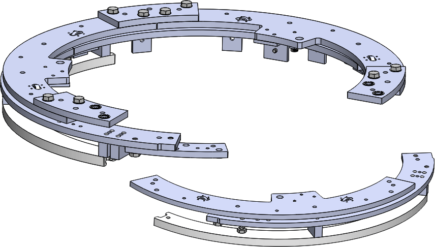
Step 2-B: Disassemble Ring Assembly To Pass It Around The Tower
Depending on the site conditions, it may be necessary to dis-assemble one third of the ring assembly (upper, lower, or both) in order to pass them around the tower. You will need to remove one section of the fixed circle, one section of the rotating circle, and one section of the plastic track. Be sure to re-assemble all of the pieces in reverse order. Note that the upper ring assembly is positioned with the plastic track pointing down and the lower ring assembly is positioned with the plastic track pointing up.
After re-assembly, torque all of the ½” bolts to 36 foot-lbs.
Step 3 – Install The Lower Pole Mount And Lower Ring Assembly
The lower pole mount assembles the same way as the upper pole mount. To simplify installation it is helpful to clock the three arms in line with the upper three arms.
The vertical spacing from upper pole mount to lower pole mount depends on if the lower ring assembly will be mounted directly or via threaded rods. It also depends on if the lower ring assembly will sit above or below the lower pole mount arms. Either one is acceptable; see General Layout Considerations.
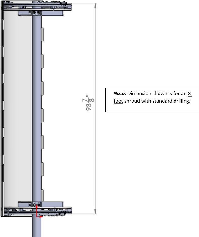
Ultimately, what matters most is the distance between the two ring assemblies. The holes in the panels are pre-drilled, and the ring assemblies will need to be spaced apart to match the hole pattern in the fixed panel.
For an eight foot panel height with standard hole drilling the distance from the top of the top fixed ring to the bottom of the bottom fixed ring should be 93-7/8”.
The lower ring assembly needs to be level, parallel to the upper ring assembly, and concentric with the tower. The same plastic alignment guide should be used before tightening the lower ring assembly to the lower mounts. It is worth spending some extra time at this stage to be sure the two rings are level, parallel, and concentric. It will make hanging the panels easier and the final installation perform smoothly.
At this point, just position the lower ring close but leave the 3 attachment points hand tight.
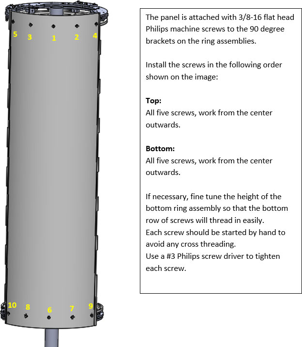
Step 4 – Install The First (Fixed) Panel
The fixed panel has ten pre-drilled holes. To identify which end is the top, note that the hinge on the right side will have a barrel at the bottom and a notch at the top.
Once the fixed panel is attached, tighten the lower ring attachment bolts, while making a final check that the lower ring is still concentric with the tower.
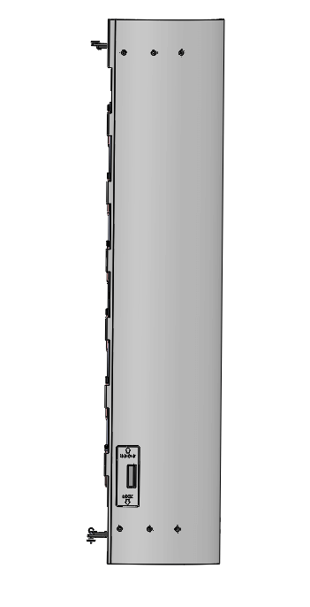
Step 5 – Install The Latch Panel
The latch panel has the handle assembly and a metal follower disc at each end. Guide the discs into the open end of the plastic track and slide the panel all the way up to the fixed panel. Lock the panel against the fixed panel using the handle and lock mechanism.
Step 6 – Install The Floating Panel
The floating panel is the one with no holes. Position it between the fixed and latch panels by aligning the hinge notches along each edge. Once it is positioned, press the ¼” diameter rods from the top of the hinge all the way down through the hinges to the bottom.
Step 7 – Final Test
This completes the Super Shroud installation. At this point, open and close the door to verify correct operation.
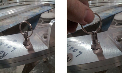
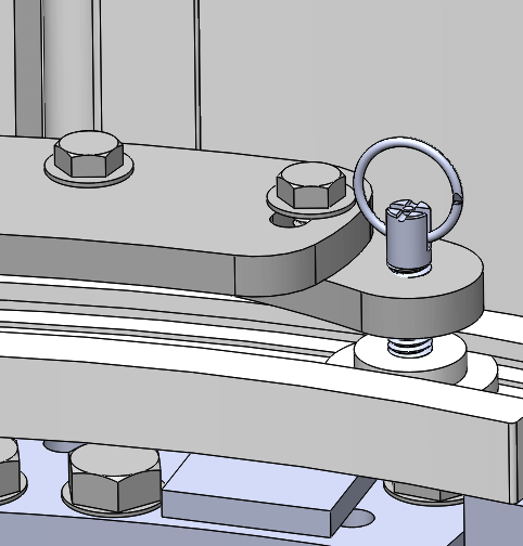
There is a spring plunger lock pin on the lower rotating ring and on the lower track arm. These are used to lock the shroud while servicing the antennas. Please note how the key ring can be raised and turned 90 degrees to disengage the lock.